Currie Enterprises has been building third members for many applications for more than 50 years, and they have a ton of different optional components available. Every customer’s specific vehicle application and needs are discussed during the ordering process to ensure that the right parts are chosen.
Hey, it can’t hurt to ask, right? However, a lot of people still think that old parts are available at local wrecking yards, and that they’ll be able to save money by adding a new housing to an old third member. Unfortunately, Currie and their suppliers are out of original Ford components for assembling third members now, and all of their components are 100-percent new. This is not a bad thing because quality and reliability are still the top priority at Currie. They have either researched suppliers that maintain and even exceed the original Ford specs, or they have taken matters into their own hands by tooling up to produce the parts in-house.
Stopping by to visit their facility in Anaheim, California, was a great experience because the shop is full of enthusiasts who take pride in building the best product at an affordable price. During my visit, I joked that they were building themselves out of business because they produce such a good product. The retort, “Who wants to build just one car in their lifetime?”
With that said, we were invited to take a trip into the shop with our camera to get a first-hand look at how to assemble a brand-new Ford-style, but Currie-built, third member gear case. Take a look at how it was done for an early model Ford Mustang project.

The gear case that was chosen belongs in an early Mustang project. Stamped on the case is the famous “N,” which stands for “nodular iron.” Although a little excessive for this application, it is a brand-new, Ford-produced case from the original “N” case tooling, and as one of the last OEM parts, we figured that all you Ford guys would enjoy it.


The pinion support is the nodular iron Daytona style. This pinion support features a larger inner bearing for increased load capacity. Stock pinion supports featured equal-size, small pinion bearings.

The yoke is a brand-new nodular iron reproduction of the stock-size yoke on a stock 9-inch-equipped car. It fits the smaller 1310 joint and is short. This yoke is also specially machined deeper in the area where the pinion nut will seat to accommodate the Daytona-style pinion support.

The carrier unit is Currie’s T.S.D. (Torque Sensing Differential) posi-traction unit. Essentially a nodular iron reproduction of an original Ford traction lock, with the exception of the T.S.D. not having the clutch pack load springs, but extra shimming instead. This provides a posi with no clutch drag like a traditional posi would have. So no tire chirps around corners and such.

Ring and pinion is a 3.70 ratio Midwest Motive Gear unit.

Posi-traction ring gear bolts have a smaller head than an open carrier ring gear bolt, and the posi bolts also take a washer.


They start to build the unit by installing the carrier bearings onto the T.S.D. posi unit in a press. Then they put red Loctite onto the ring gear bolts and install them into the ring gear with an impact wrench.

Cross-torquing them from side to side gradually pulls the ring gear onto the carrier. They finish by torquing them to proper specs with a torque wrench.


Next, they press the large pinion bearing onto the pinion gear. Then they install the pinion support, pinion depth shims and solid spacer, and the outer bearing onto the gear. Next they press on the outer bearing. Here’s a look at the completed unit.


The pinion seal is now installed. They use a hammer and their own custom seal driver tool (the last photo shows the seal installed).

Here a set-up yoke is installed onto the pinion gear with an impact.


An O-ring is installed onto the back side of the pinion support; this seals the pinion support to its machined bore in the gear case.


In this photo you can see the pocket bearing and pocket bearing retainer.
They’ll install the pocket bearing and pocket bearing retainer into the gear case by dropping the bearing into the hole, like so.


A driver tool is used to install the bearing, and then the same driver tool is used again to install the retainer. Here you can see the bearing and retainer installed.


The bore in the front of the gear case is greased in preparation for the pinion support installation. Proper pinion depth shims for the selected components are installed onto the pinion support mounting surface.

Now, the pinion support/pinion gear assembly is dropped in and checked to see how freely the pinion spins. It’s common that the casting may need to be trimmed to ensure that the retainer for the pocket bearing fits and allows the pinion to spin freely. Again, this is common, but can only be checked by installing and even reinstalling the pinion gear until it’s right.

.The next step is to drop in the carrier/ring gear unit and do the preliminary spanner nut adjustments


The carrier unit is removed because it hits a casting line on the inside of the gear case. Using a die grinder, they clean up the casting line. Here’s a look inside the case after grinding. Essentially, every case casting is different, and every optional carrier is different and every ring gear of a different ratio is a different diameter—it is very common for cases to have to be ground to fit different carriers and different ratio gears.


Now, the carrier/ring gear assembly is dropped back in, and the technician feels for initial backlash by hand. Red Loctite is used on the carrier cap bolts, which are then dropped onto the unit. The technician then snugs them up, but does not torque at this time.


A dial indicator is used to get exact backlash, and it is adjusted by turning the spanner nuts with a spanner wrench. Seen here, we can tell you just how good these guys are because they achieved the gear manufacturer’s recommended backlash on the first try!


Before running the pattern on the gears, they paint white marking compound onto a small section of the ring gear teeth, then they put grease onto most of the remaining teeth of the ring gear. This allows the grease to make a footprint onto the white marking compound when the pattern is run.


An electric motor is used to spin the third member over to run the pattern. Once again, the pros here at Currie nail it on the first try, so no additional tuning is necessary.


Blue Loctite is applied to the spanner nut retainer bolts, and then the retainers are installed onto the carrier caps. Now that everything has checked out fine, we go back to torque the carrier cap bolts. Then the new pinion support bolts are installed and torqued. Lastly, they remove the set-up yoke, grease the new yoke and install it. To keep the pinion nut tight, an impact gun is used.


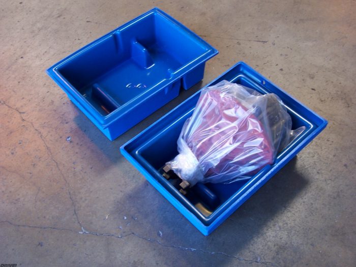
The completed unit is lifted off the bench and set onto a painting cart where they finish painting it to protect the nodular iron from the elements. After painting the unit, it’s then bagged, sealed and packaged in a shipping crate awaiting the big brown truck to deliver it to its new home.
Currie Enterprises
714.982.5302
Currieenterprises.com
Text by Marcel Venable and Photos by the MCP staff